Quick Specs
| Current Rating | 100 to 300 amps |
|---|---|
| Operating Voltage | 7.5 to 36 VDC |
| Voltage Drop at Max Current | 30mV |
| Temperature Range | -40 to +105 C |
| Weight | 26 ounces |
| Dimensions | 5.8″ x 3.1″ x 2.1″ |
- ***Note: Generation 3.0 not for new applications***
- No longer in active production, but can be made-to-order under special circumstances
- An ideal high current dual-diode configuration
- Charges two batteries or banks from a single charging source
- Allows independent discharge of each battery or bank
- Allows each battery or bank to absorb current as needed
- Industry-leading ultra-low voltage drop
- Extends battery life by insuring full charging voltage reaches the batteries
- 99.9% efficient at maximum continuous current
- No heat sinks or airflow required
- No de-rating required over full temperature range
- Fully encapsulated solid state design
- Internationally patented MOSFET technology
- Recommended by top battery manufacturers
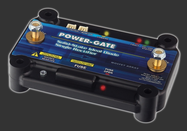
A dual rectifier has all the same outstanding performance characteristics of a single rectifier, but provides discharge protection for two batteries; two, one-way electrical valves in a single package. DC current will flow from the alternator to the batteries, but current will not flow between the batteries when discharged. Dual rectifiers are commonly deployed in dual battery configurations where each battery may be discharged independent of the other.
A common problem with conventional “marine” or “RV”; style isolators (aside from performance issues related to the obvious voltage drop and associated heat) is dealing with an internally regulated alternator. A dedicated excitation circuit insures hassle-free integration with internally regulated alternators. Ultra-low on-resistance means devices require no heat sinking and no airflow at currents up to 300 amps. . Dual rectifiers are epoxy encapsulated in a custom ABS enclosure and are well suited for hostile environments. POWER-GATE is recommended by top battery manufacturers to insure that DC power gets to where it’s needed without the excessive heat and voltage loss typified by more common, lesser performing silicon and Schottky devices.
Included on every POWER-GATE Dual Rectifier is a violet Alternator excitation wire. When system voltage (12 or 24 volts respectively) is applied, the MOSFET array located between the Main battery cathode and Alternator input anode is enhanced for a period of 60 seconds. This trigger is initiated when the violet wire is momentarily connected to the engine start circuit typically tapped at the starter solenoid, or the wires leading to the starter solenoid. When triggered, the user will note a four second delay between trigger initiation and alternator excitation. The purpose of this circuit is to insure the Alternator’s regulator excites at vehicle start-up. If the starter circuit is inaccessible, the device can be factory programmed for an alternate trigger like switched system voltage from an accessory port. If an alternate trigger configuration is required, contact engineering to discuss your needs.
When the Battery Combine Feature is activated, the default isolation mode is temporarily overridden and both MOSFET arrays are forced into the energized mode. This causes the batteries to combine. For example, if the main starting battery is discharged to the point where the vehicle won’t crank, by pressing a mini logic-level momentary switch, the Battery Combine feature will enable the auxiliary battery to pass current to the main starting battery, at which point cranking can take place. Once the vehicle is started, release the momentary switch and POWER-GATE will default back to its full isolation mode.
Dual Rectifiers can handle between 100 amps and 300 amps.
For OEM applications, military and fleet sales, special applications, or general questions call us 858.720.1339.