Quick Specs
| Current Rating | 100, 150, 200, 250, 300 amps |
|---|---|
| Surge Current | up to 1,500 amps |
| Operating Voltage | 5.6 to 36 VDC |
| Voltage Drop at Max Current | 30 mV to 49 mV |
| Temperature Range | -40 to +85 C |
| Weight | 23.5 ounces |
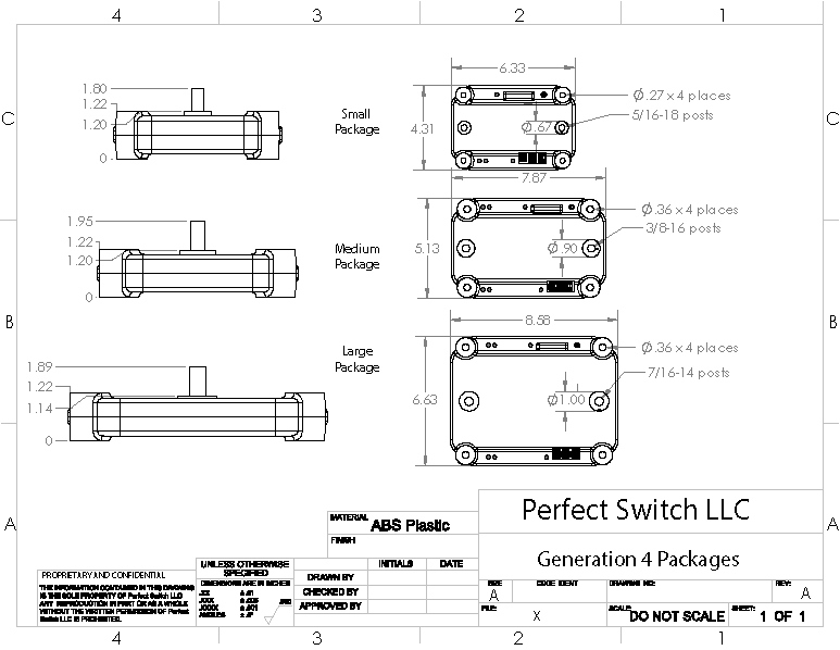
| Dimensions | 7.78” x 5.13” x 1.95″ |
- GENERATION 4.1
- Larger posts for improved electrical and thermal conductivity.
- Lower voltage drop at elevated temperatures for greater longevity
- Reverse battery connection protection (no onboard fuse necessary)
- User selectable Alternator excitation for ultimate installation flexibility
- Remote LED installation harness (optional) for driver-centric monitoring of rectifier status
- Market-leading, ultra-low on-state resistance
- Charges two batteries or banks from a single charging source
- Battery combine feature for self-jumping
- Ideal high current dual-diode configuration
- Allows independent discharge of each battery or bank
- Allows each battery or bank to absorb current as needed
- Extends battery life by ensuring full charging voltage reaches the batteries
- 100% solid state, no moving parts to wear
- 99.9% efficient at maximum continuous current
- No heat sinks or airflow required
- No de-rating required over full temperature range
- Expansion port for external monitoring display (coming soon)
- Beefy 3/8-16 x .75″ brass connection posts for large lugs
- CNC cut and plated internal conductors optimized for high current transfer
- Hi-temp polycarbonate injection molded shell
- Fully encapsulated rough-duty design
- Dow Corning aero-qualified silicon potting
- Internationally patented MOSFET technology
- Recommended by top battery manufacturers
Quick Links
Need Help?
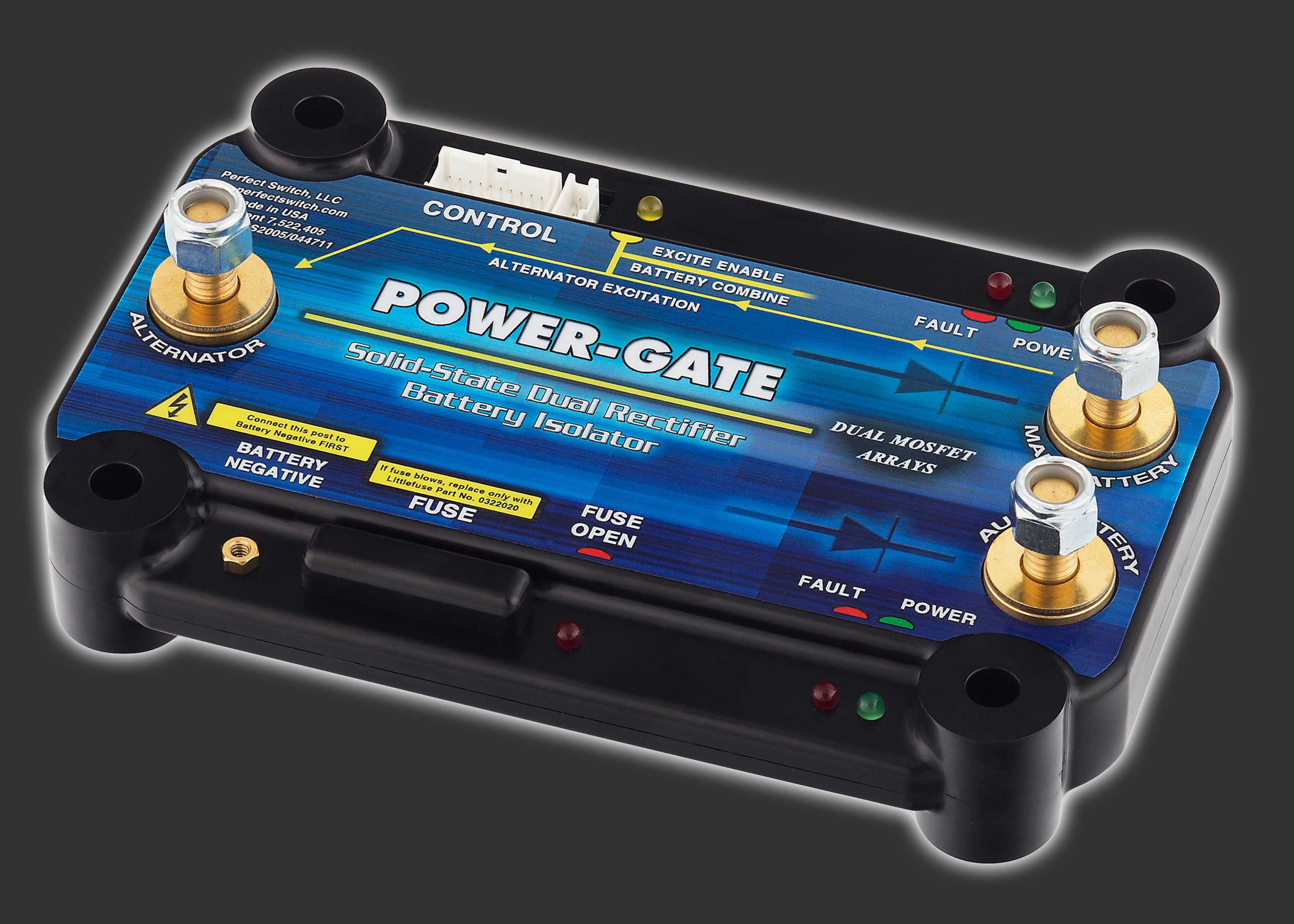
A dual battery/dual rectifier/ dual battery isolator has all the same outstanding performance characteristics of a single rectifier, but provides discharge protection for two batteries; two, one-way electrical valves in a single package. DC current will flow from the alternator to the batteries, but current will not flow between the batteries when discharged. Dual rectifiers are commonly deployed in dual battery isolator configurations where each battery may be discharged independent of the other.
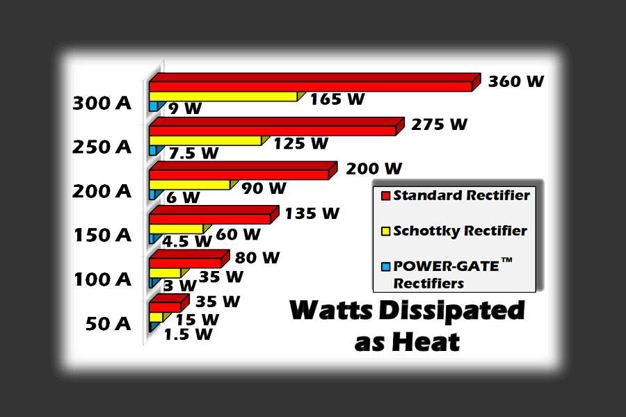
A common problem with conventional “marine” or “RV”; diode-style isolators (aside from performance issues related to the obvious voltage drop and associated heat) is dealing with an internally regulated alternator. Two dedicated alternator excitation circuit options ensure hassle-free integration with internally regulated alternators, “smart” alternators, and computer controlled alternators. Ultra-low on-resistance means devices require no heat-sinking and no airflow at full continuous current. . Dual rectifier dual battery isolators are fully encapsulated using an aerospace qualified silicone elastomer specifically developed for potting electronic modules and inserted into polycarbonate enclosure well suited for hostile environments. POWER-GATE is recommended by top battery manufacturers to insure that DC power gets to where it’s needed without the excessive heat, voltage loss, and amperage loss typified by more common, lesser performing silicon and Schottky devices built on large aluminum extrusions.
Included on every POWER-GATE Dual Rectifier are two different alternator excitation triggers for ultimate installation flexibility. When system voltage (12 or 24 volts respectively) is applied, the MOSFET array located between the Main battery (cathode) and Alternator input (anode) is pulsed on while concurrently sensing if the alternator is generating voltage. The preferential alternator excitation trigger is initiated when the Orange wire is momentarily connected to the engine start circuit typically tapped at the starter solenoid, or the wires leading to the starter solenoid. When triggered, the user will note a four second delay between trigger initiation and alternator excitation. The purpose of this circuit is to insure the Alternator’s regulator excites at vehicle start-up. If the starter circuit is inaccessible, the installer may use the Violet wire which is an alternate trigger using ignition switched system voltage from an accessory port. If momentary starter and ignition switched are unacceptable, contact engineering to discuss your needs.
Battery Combine Feature
New is the addition of a standard Battery Combine feature. When the Battery Combine Feature is activated, the default isolation mode is temporarily overridden and both MOSFET arrays are forced into the energized mode. This causes the batteries to combine. For example, if the main starting battery is discharged to the point where the vehicle won’t crank, by pressing a mini logic-level momentary switch, the Battery Combine feature will enable the auxiliary battery to pass current to the main starting battery, at which point cranking can take place. Once the vehicle is started, release the momentary switch and POWER-GATE will default back to its full isolation mode.
Dual Rectifier dual battery isolators are built in our medium package in configurations of 100 amps, 150 amps, 200 amps, and 300 amps. For currents greater than 300 amps, please view our Large Package Dual Rectifier.
Need help configuring a Dual Rectifier? Click Here.
For OEM applications, military and fleet sales, special applications, or general questions call us 858.720.1339.