Description
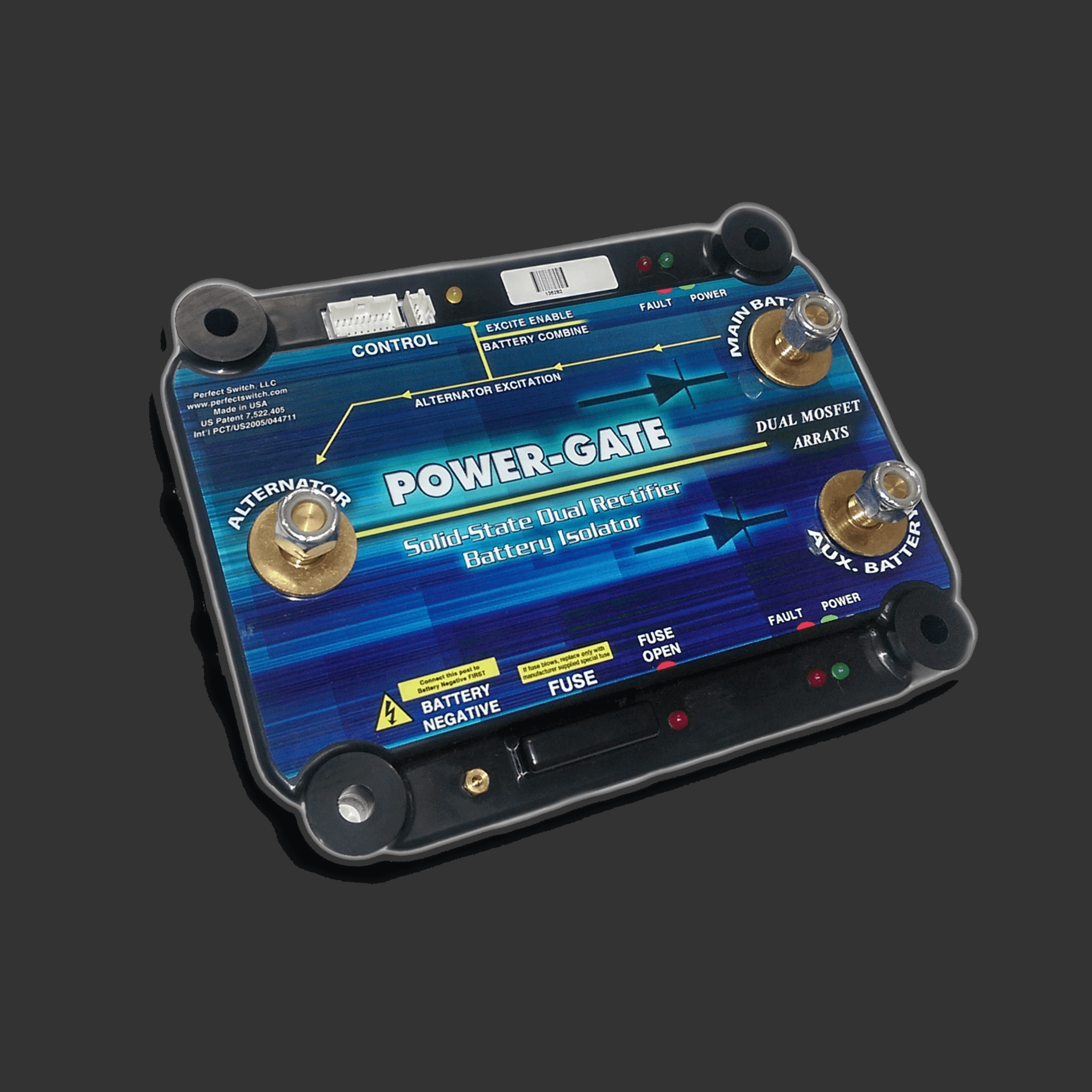
Dual Rectifier, dual high current MOSFET arrays for 400, 500, and 600 amp applications. Note that Generation 4.1 Dual Rectifier devices have both on-board LEDS, and external LEDS can be activated using the optional wire harness. Also note that standard on Generation 4 devices are battery combine trigger, and two types of alternator excitation triggers.
- Battery Combine Trigger forces the MOSFET arrays to turn-on which then, in turn, combines the main and auxiliary batteries. When pins 1 and 2 (black and green) are shorted, combine is active. When the connection is open, combine is disabled and default isolation takes place. Perfect Switch recommends the use of a momentary switch to insure the battery combine feature is not accidentally left on.
- Alternator excitation trigger is necessary for most alternator voltage regulators to “turn-on” during the vehicle starting process. Although some external regulators do not require this trigger, all internally sensed internal voltage regulators do require excitation.
- IGNITION ALTERNATOR EXCITATION (violet wire):
Upon application on the ignition line of a voltage greater than the turn-on threshold (~2 V), the device will first wait four seconds before initiating the alternator excitation sequence. This allows cranking to occur without a possible depleted auxiliary battery loading down the engine. After the four seconds has elapsed, the MOSFET array connected to the main battery will turn on to connect the battery to the alternator, allowing the regulator to begin operation. The array will remain on for approximately half a second; during this time, the device will be looking for the moment when the alternator voltage rises above that of the main battery. If this occurs, the excitation sequence is ended and the device will transition into its standard ideal diode mode. If not, once the half-second on-time has elapsed, the main array will shut off. Approximately 3 seconds later, the device will try exciting the alternator once again (with a half-second on-time). This process will occur a maximum of five times; if the alternator fails to begin charging after the fifth time, the device will immediately go to sleep and wait for another positive-going ignition signal. The user will note the Yellow LED will be on when the excitation sequence is active. - STARTER ALTERNATOR EXCITATION (orange wire): Upon application on the starter line of a voltage greater than the turn-on threshold (~2 V), the device will wake up from its sleep mode and wait for a disappearance of the starter signal, indicating the starter has been released and, presumably, the cranking process has completed. The device will then wait four seconds before initiating the alternator excitation sequence. After the four seconds has elapsed, the MOSFET array connected to the main battery will turn on to connect the battery to the alternator, allowing its regulator to begin operation. The array will remain on for approximately one-half second. During this time, the device will be looking for the moment when the alternator voltage rises above that of the main battery. If this occurs, the excitation sequence is ended and the device will transition into its standard ideal diode mode. If not, once the half second on-time has elapsed, the main array will shut off. Approximately 3 seconds later, the device will try exciting the alternator once again (with a half-second on-time). This process will occur a maximum of five times; if the alternator fails to begin charging after the fifth time, the device will immediately go to sleep and wait for another positive-going starter signal.