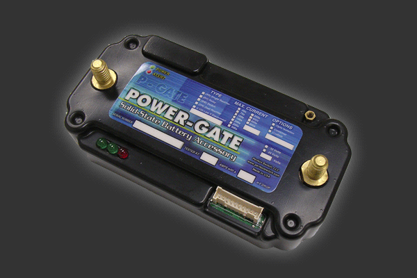
POWER-GATE Solid State Relays are constructed based on our patented arrayed MOSFET technology. MOSFET transistors have an integrated body diode and depending on the application’s direction of current flow, two primary configurations of POWER-GATE Relays are offered: uni-directional and bi-directional. All relays can be manually controlled, autonomously controlled, or a mix of both manual and automatic features. The following programmable features are available for application specific customization:
- Up to four (4) levels of Undervoltage Shutdown (volts), Undervoltage Delay (time), Undervoltage Reset (volts), Undervoltage Reset Delay (time)
- Up to four (4) levels of Overvoltage Shutdown (volts), Overvoltage Delay (time), Overvoltage Reset (volts), Overvoltage Reset Delay (time)
- Circuit Breaker Shutdown (amps), Circuit Breaker Shutdown Delay (time)
- Sleep Mode
Uni-Directional Relays
Uni-Directional Relays are designed to sit between a source and a load. Some examples would be a relay placed between a battery and a motor, or between a battery and an inverter. Current will only flow in one direction from the battery to the load its powering.
Uni-directional relays can be controlled manually, triggered when the user applies system voltage to the device’s trigger input (or optionally low-side triggered). When trigger is applied, the relay closes (conducts current), and when trigger is removed, the relay opens (ceases to conduct current). They can also be configured to work autonomously where the on-board micro controller decides when to conduct current, or not to conduct current based on system voltage, timing, or current cues. With this kind of flexibility built into every relay, devices can be configured to serve as:
- Low Voltage Disconnects (LVD). Placed between a battery and loads, the device will allow the battery to power accessories connected to the output of the relay. If the battery voltage dips below a specific low voltage threshold, the relay will open and stay open until the voltage is sensed to be above a specific turn-on voltage. For example, the relay can be used to power several hundred amps of accessories connected to the relay output. On a 12 volt system, if the voltage drops to 12.3 volts for at least one minute, the device will sense that as a stable, low voltage condition and open the relay. The relay will stay open until the system voltage is sensed to be 13.0 volts indicating a charging source has been applied. When 13.0 volts is sensed, the relay will close restoring the connection between the accessories and the battery. Low voltage disconnects are common in marine and fleet applications and are often called LVD’s or voltage sensitive relays. POWER-GATE is far more than just a low voltage disconnect as it can provide both low and high voltage disconnect functionality, under and over current functionality, handle in-rush current, and provide short circuit protection, all in a compact and ultra-efficient module.
- Programmable Autonomous Relays Placed between a battery and loads, the relay can be factory programmed to respond to under-voltage, over-voltage, under-current, over-current, or provide logic feedback to the user’s system. When configured as a programmable autonomous relay, let us know what you need and we’ll program the device to suit your application.
- Circuit Breakers. Placed between a source and loads, the device can be programmed to differentiate between typical in-rush conditions, and an over-current or shorted condition which causes the relay to open ceasing current conduction between the source and load. Once open, it’s typically programmed to stay latched open until a reset signal is applied. Think of it as a very smart, very flexible, very fast circuit breaker.
- Standard Relays. Placed between the source and load. Much like typical relays where the user applies system voltage to the device’s trigger input so the relay closes and conducts current. Removal of the trigger opens the relay so it ceases to conduct current. We offer active high trigger, active low trigger, and just about any configuration to suit your application’s needs.
- Bi-Directional Relays are designed for bi-directional current flow and are designed to sit between two voltage sources. Some examples would be a relay placed between two batteries where current could flow from battery A to battery B and visa-versa, or between a battery and an inverter/charger when current will flow from the battery to the inverter during the conversion from DC to AC, but the relay will also have to allow charging current to flow from the inverter to the battery when the inverter/charger is actively charging the battery. A back-to-back MOSFET configuration enables current to flow in a bi-directional fashion.

